| For those who have visited my
site before, the idea of a water level indicator for the fresh water tanks
was brought to my attention by Fred
Camper on the Pop Up Times Message board. The
homemade system at the bottom of this page was designed by Fred and I
posted it for him here in late 2002.
Now, if you have a tank that is above the floor, i.e. in one of your
cabinets and is easily visible this modification would not be for
you. Most Coleman tanks as well as several other manufacturers are
installed hanging from the floor. The only way to know when it is
empty is to look underneath the pop up or wait for the pump to run
dry. For me, that is usually when I'm brushing my teeth.
Obviously the original web page caught
some peoples attention, because in early May 2003 I received an e-mail
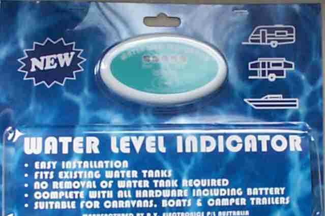
from a foreign manufacturer of a commercial water level meter. Many of you know how I
love my toys and modifications, so I responded to their e-mail. After
several back an forth e-mails, I had a water level indicator of my
own! Manufactured by RV
Electronics in Australia, this appears to be a well though out, well
made product.
meter. Many of you know how I
love my toys and modifications, so I responded to their e-mail. After
several back an forth e-mails, I had a water level indicator of my
own! Manufactured by RV
Electronics in Australia, this appears to be a well though out, well
made product.
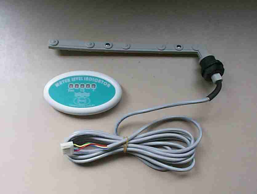
The indicator consists of a water level
sending unit which you install through the side of your tank with a wire
that connects to a level indicator that you can place inside the pop
up. By a simple push of a button I can now see how much water is in
the tank without crawling under the pop up.
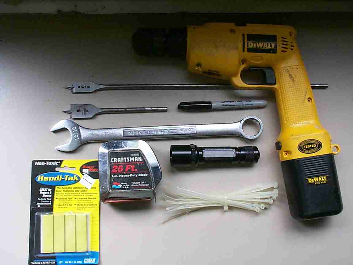
So, how hard was it to install you
ask?? Easy!!!! On my "pop up" scale,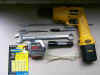 it's a 2, only because you should be comfortable with tools to do it. The
tools you need include a drill, 7/8" spade bit, 5/8" spade bit
flashlight, 15/16" wrench, measuring tape, and marking pen. I
added wire ties and "quick tack" compound.
it's a 2, only because you should be comfortable with tools to do it. The
tools you need include a drill, 7/8" spade bit, 5/8" spade bit
flashlight, 15/16" wrench, measuring tape, and marking pen. I
added wire ties and "quick tack" compound.
As you read the instructions, please note
things I have highlighted. If I identified a passage with BOLD or italics,
please pay particular attention. Failure to do so may result in
you needing to buy a new water tank.
Installation
Instructions
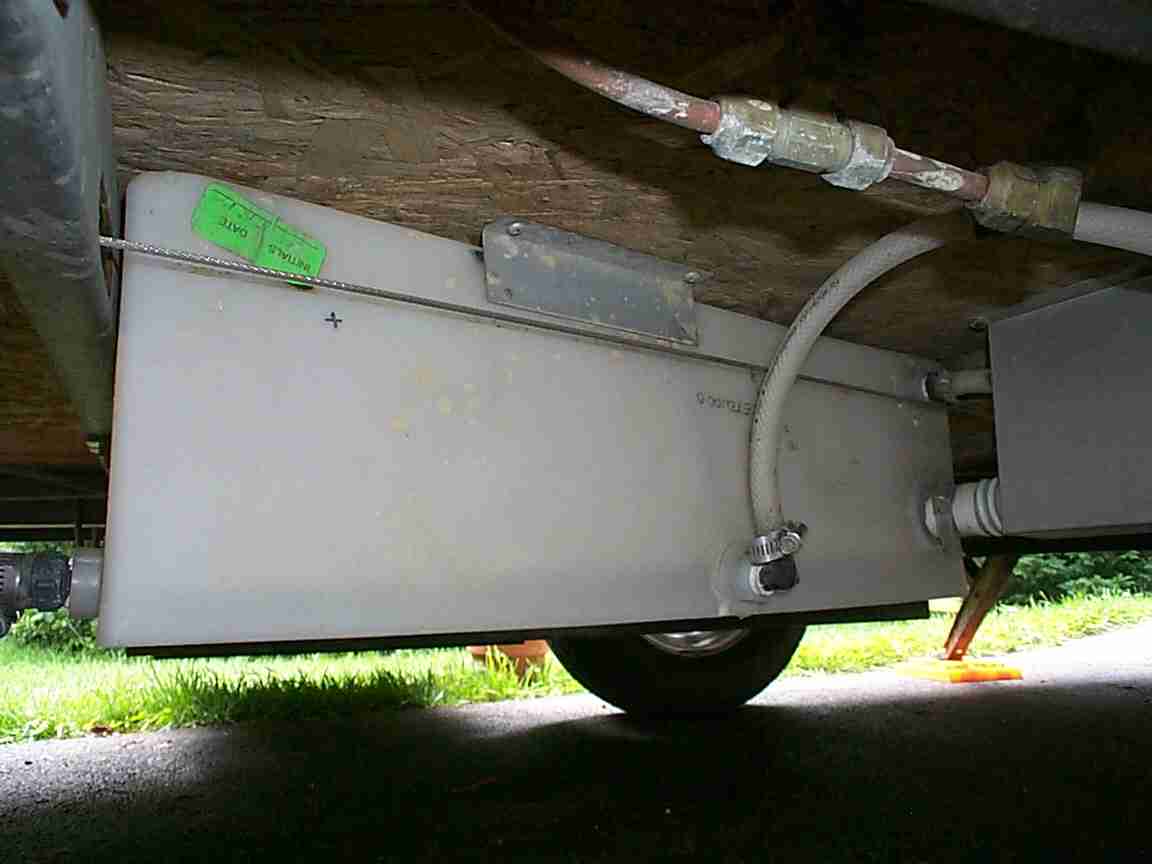
The first thing you need to do is crawl
under the pop up and look at your tank You need a minimum of 240mm
(I told you it was a foreign company)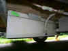 clearance from the right edge to the point you are going to install it
in. I had to run to a metric
to imperial calculator to find out that that is about 9.44
inches. I was in luck so far, the side I wanted to install it in was
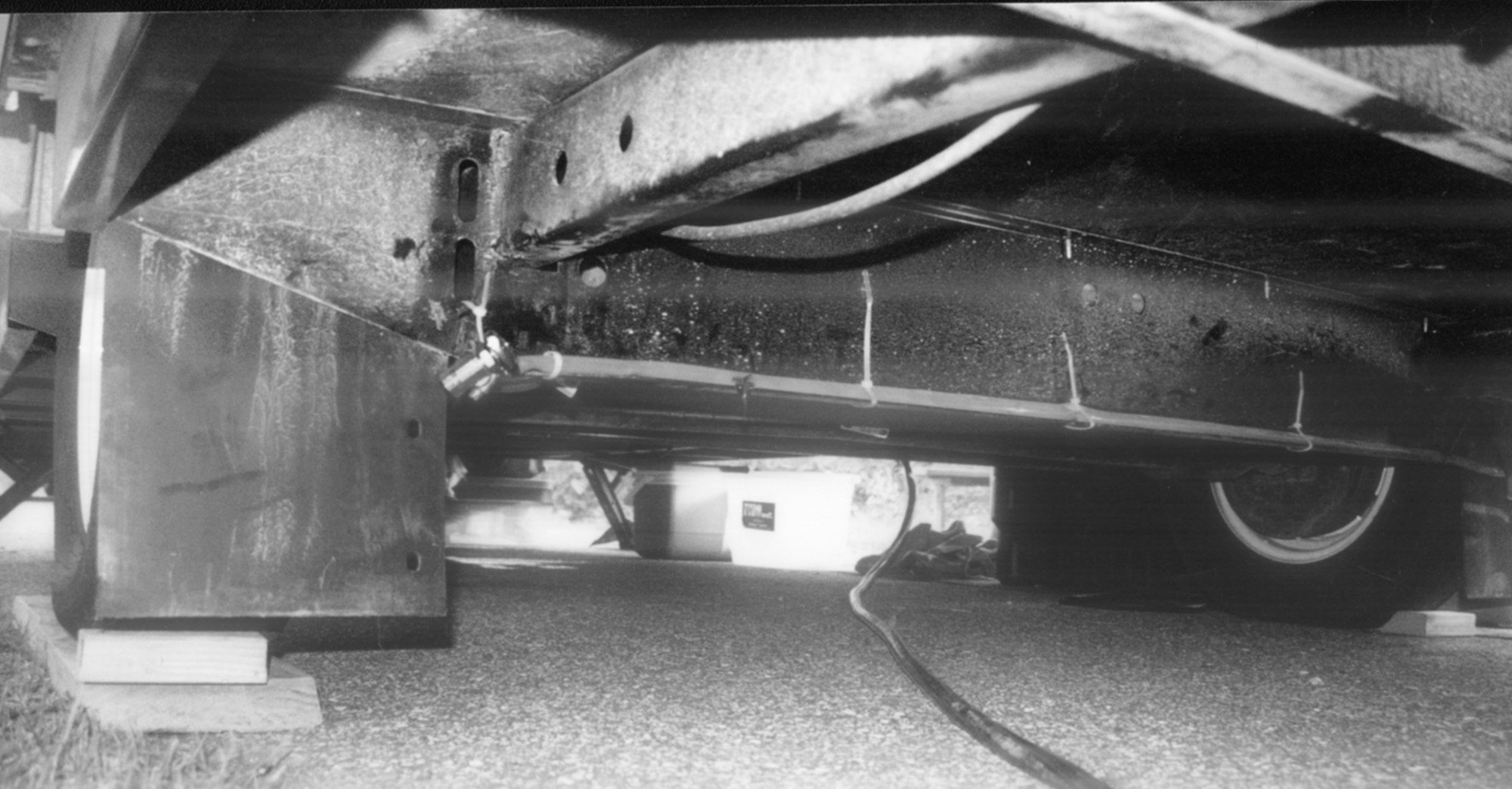
about two feet wide. To the left you see the 20 gallon tank on my
Coleman Santa Fe, looking at it from the street side. The white hose
you see is the feed tube from the bottom of the tank going up through the
floor to the swing level galley. The only problem I saw was the
silver cable you see in the picture, this is the roof cable for the front
of the pop up and it ran about one inch from the side of the tank.
clearance from the right edge to the point you are going to install it
in. I had to run to a metric
to imperial calculator to find out that that is about 9.44
inches. I was in luck so far, the side I wanted to install it in was
about two feet wide. To the left you see the 20 gallon tank on my
Coleman Santa Fe, looking at it from the street side. The white hose
you see is the feed tube from the bottom of the tank going up through the
floor to the swing level galley. The only problem I saw was the
silver cable you see in the picture, this is the roof cable for the front
of the pop up and it ran about one inch from the side of the tank.
I measured the location I wanted (remember
at least 9.44 inches clearance to the right of the hole) and 3/4 of the
way up the tank, which for me was 5 1/2 inches. Darn, right next to
the lift cable. OK, I dropped mine down about 1/4 inch).
remember the old carpenters rule, Measure Twice, Cut Once! Make
sure you know where you want to drill. If you look just below the
green label in the picture above you will see the "X" where I
plan to drill. OK, now that you think you know where you are going
to drill, take your flashlight and closely examine the tank. Some
tanks have center dividers for additional strength. Remember you
need 9.44 inches clearance to the right of the hole you drill. If
there is a center divider in the way it will interfere with the sending
unit!
OK, once you are sure of the sending unit
location you need to figure the route the wire is going to take to the
indicator location inside the pop up. I decided to put it on the
front of the lower section of the swing level galley, so I was in
luck. The galley was right above the location I picked to drill a
hole. Additionally, I was able to find a wire route next to the LP
Gas lines for my furnace and hot water heater. Make sure you will
have sufficient wire length to run from sending unit to your chosen
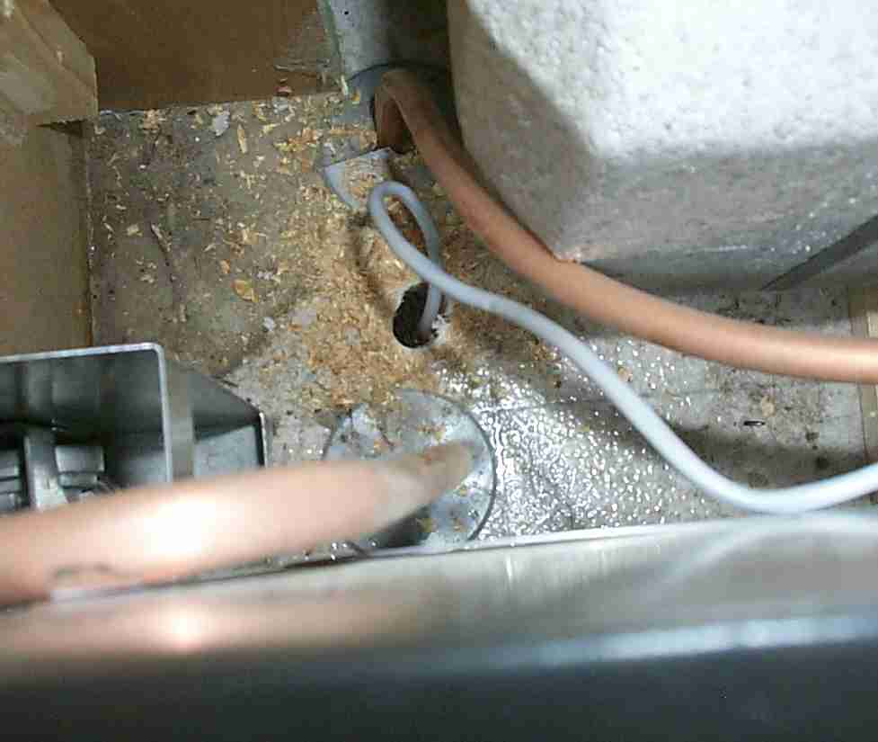
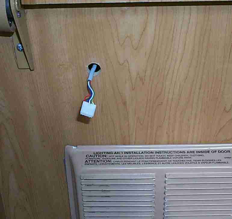
location for the display. The wire supplied is over 8 feet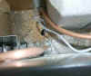 long and I found this to be plenty of wire to route it to a mounting
location. In the photo to the right you see the hole I drilled
through the floor to route the wire. I used a ?? spade bit which
just barely provided space to run the wire/connector through the
hole. Note, this photo is inside the galley base cabinet, so the
hole will be hidden from view.
long and I found this to be plenty of wire to route it to a mounting
location. In the photo to the right you see the hole I drilled
through the floor to route the wire. I used a ?? spade bit which
just barely provided space to run the wire/connector through the
hole. Note, this photo is inside the galley base cabinet, so the
hole will be hidden from view.
Now, I know I can get the wire from the
tank to the indicator and I'm sure that there is clearance inside the
tank, 9.44 inches to the right of the hole. It's time to
drill. Using a 7/8" spade bit - SLOWLY drill through the side
of the water tank at your selected location. Going slowly will allow
you to keep most of the plastic out of the tank.
OK, now you have a hole in the side of
your tank. It's time to install the sending 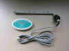 unit.
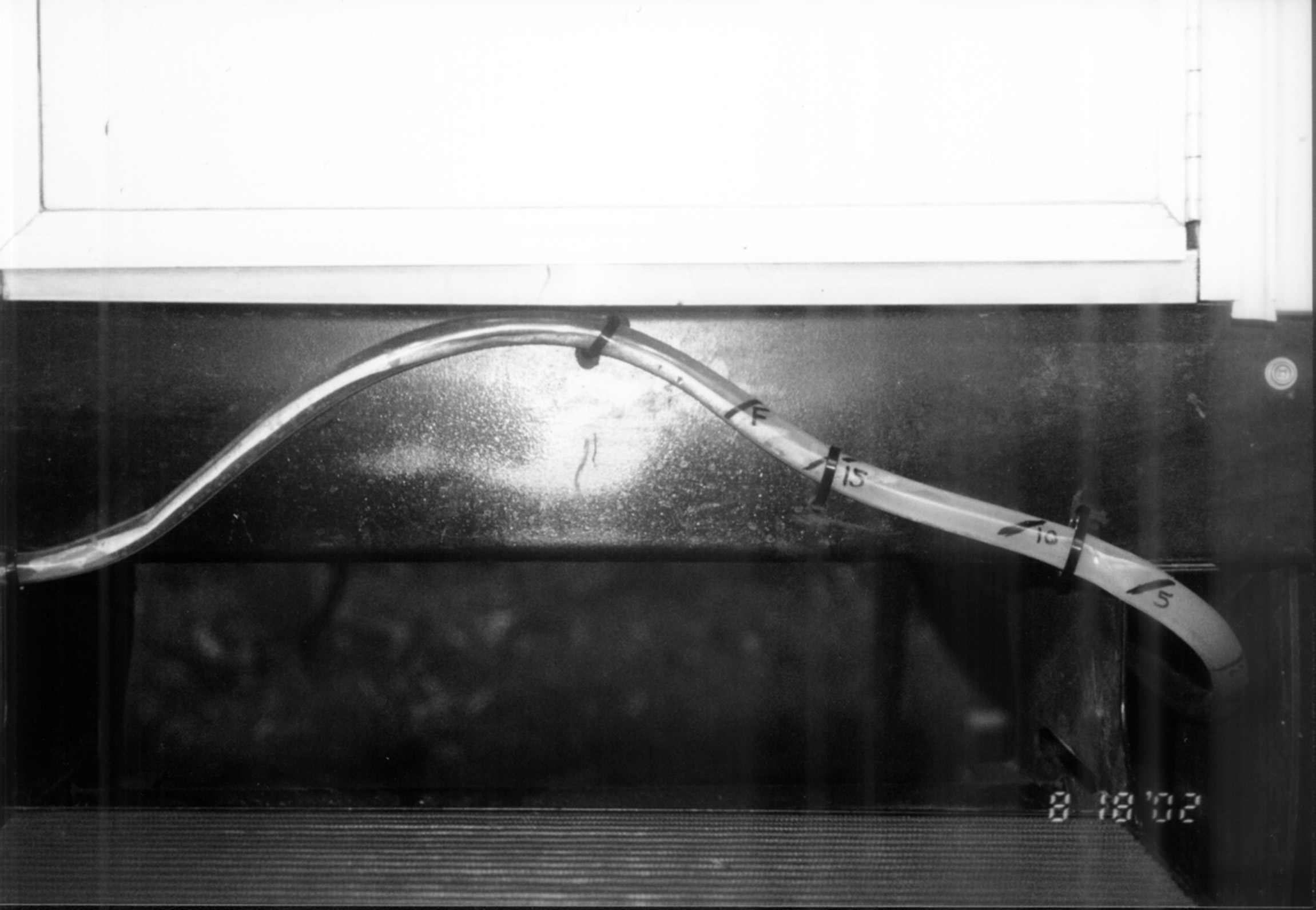
In the picture to the left, the sending unit is the grey (gray) plastic
"stick" with a wire hanging out of it. It is an electrical
probe sensing unit, not a float type device. You insert it into
the tank pointing to the right. You do have 9.44 inches to get it in
there don't you? Now you get to use the wrench. The black
plastic bushing has a self sealing ring. As you tighten up the nut,
the ring expands inside the tank, sealing the hole you drilled. DO
NOT OVER TIGHTEN THIS NUT! Additionally as you tighten it, the
sending unit slowly swings down so that the grey stick is now somewhere
between 45º and vertical. With the sensors along the length of the
shaft, it can now sense the amount of water in the tank, sending that
information to the display. unit.
In the picture to the left, the sending unit is the grey (gray) plastic
"stick" with a wire hanging out of it. It is an electrical
probe sensing unit, not a float type device. You insert it into
the tank pointing to the right. You do have 9.44 inches to get it in
there don't you? Now you get to use the wrench. The black
plastic bushing has a self sealing ring. As you tighten up the nut,
the ring expands inside the tank, sealing the hole you drilled. DO
NOT OVER TIGHTEN THIS NUT! Additionally as you tighten it, the
sending unit slowly swings down so that the grey stick is now somewhere
between 45º and vertical. With the sensors along the length of the
shaft, it can now sense the amount of water in the tank, sending that
information to the display.
Once the sending unit is installed, route
the wire through the floor into the cabinet you plan to mount it to.
Secure the wire under the floor of the pop up to assure that it will not
snag on anything as you travel. As my wire route was next to LP Gas
pipes I was able to use wire ties to secure it under the pop up.
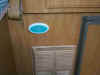
Now it is time to drill a hole through the
cabinet you plan to mount the display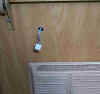 on. Us the same spade bit you used on the floor, this time through
the cabinet face. Make sure you have sufficient clearance from and
moving parts like cabinet doors or in my case the LP Gas furnace.
For this reason I also used tie wraps and quick tack to secure the wire
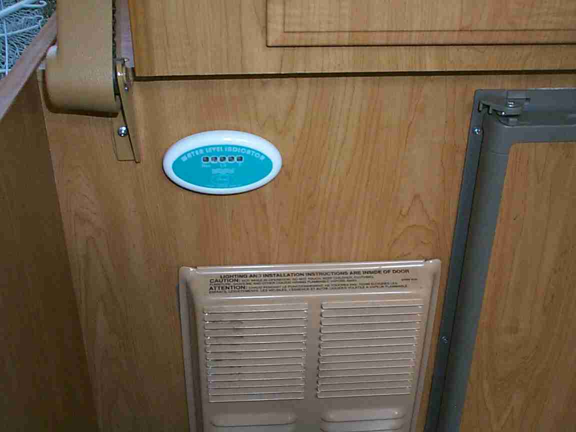
out of the way of moving parts and the furnace. Here you see the connector
on the end of the wire hanging out of the hole I drilled just above the
furnace. This connector plugs into the rear of the display and the
display attached to the front of the cabinet with double sided tape
(provided).
on. Us the same spade bit you used on the floor, this time through
the cabinet face. Make sure you have sufficient clearance from and
moving parts like cabinet doors or in my case the LP Gas furnace.
For this reason I also used tie wraps and quick tack to secure the wire
out of the way of moving parts and the furnace. Here you see the connector
on the end of the wire hanging out of the hole I drilled just above the
furnace. This connector plugs into the rear of the display and the
display attached to the front of the cabinet with double sided tape
(provided).
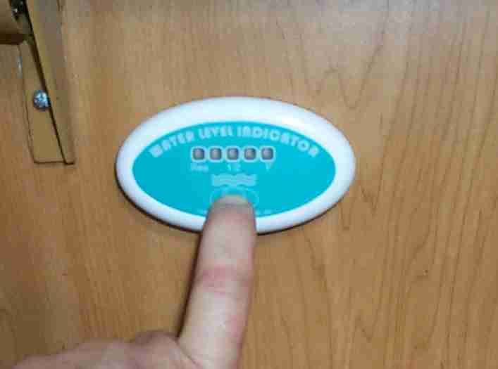
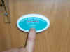  Now,
with a simple push of a button I can tell how much water is in my
tank. It has LEDs to indicate the amount of water from "Res"
(reserve or empty) to "F" for full. It is powered by a
standard A23 battery which should give plenty of time before battery
replacement. Now,
with a simple push of a button I can tell how much water is in my
tank. It has LEDs to indicate the amount of water from "Res"
(reserve or empty) to "F" for full. It is powered by a
standard A23 battery which should give plenty of time before battery
replacement.
The instructions with the unit were printed on the back of the box, but
I found them clear and easy to follow. If I had not been stopping to
take pictures as I worked, the installation the entire project should have
only been about 30 minutes. As it was I completed it in less than
one hour. Prior to making this modification you should be
comfortable with hand tools. Read and understand all written
instruction of the manufacturers packaging.
|